深度和法线纹理为游戏开发过程中常用的信息,通常情况下存储在深度法线纹理中,使用时需要进行对应的转换。
简介
- 在游戏开发过程中,深度和法线信息起着重要的作用。在渲染管线中,深度和法线通常会存储在深度法线纹理中,供各个阶段使用。其中,纹理的生成规则和使用方式相互关联,为了能够了解其使用方法,需要认识其生成过程。
深度纹理
深度值
正交投影
- 经过投影变换和齐次除法后,可以得到裁剪空间下的深度
z_NDC 其中
其中 z_view为观察空间下的深度。 - 在像素着色器中,每一个像素的坐标都需要通过插值计算得到。然而,计算结果的值存储在
z-buffer中,渲染管线通常不能直接进行操作,因此需要存入到深度纹理中。由于深度纹理的范围为[0, 1],因此深度纹理中的z_depth值为
- 由于 OpenGL 中观察空间为右手坐标系,而裁剪空间下是左手坐标系,所以观察空间下的
z_view值需要取反,才为左手坐标系下的线性z_eye值,即
- 在
com.unity.render-pipelines.core/ShaderLibrary/ShaderVariablesFunctions.hlsl中,获取线性深度的方法为
// ShaderVariablesFunctions.hlsl
...

float LinearDepthToEyeDepth(float rawDepth)
{
    #if UNITY_REVERSED_Z
        return _ProjectionParams.z - (_ProjectionParams.z - _ProjectionParams.y) * rawDepth;
    #else
        return _ProjectionParams.y + (_ProjectionParams.z - _ProjectionParams.y) * rawDepth;
    #endif
}

...
- 其中,用于在 shader 中计算深度的
_ProjectionParams参数值为
透视投影
- 透视投影下的裁剪空间深度
z_NDC
- 在像素着色器中,每一个像素的坐标都需要通过插值计算得到。而在透视投影下,需要使用透视校正插值。如果深度纹理使用观察空间下的
z_view,则在插值过程顶点坐标需要除以z_view,因此深度纹理使用z_NDC可以减少计算复杂度。 - 齐次除法后的
z_NDC值已经不为观察空间下z_view值的线性变换,因此使用深度纹理的深度信息时,需要变换观察空间下才能进行其他计算,即 则
则 z_eye为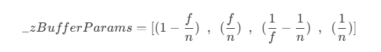
- 当相机位置为 0 ,远裁剪平面为 1 时,即在左手坐标系下整体缩小
f,则深度值z_linear01为
- 当近裁剪平面为 0 ,原裁剪平面为 1 时,即在左手坐标系下先移动
-n,再整体缩小f,则深度值z_linear01FromNear为
- 在
com.unity.render-pipelines.core/ShaderLibrary/Common.hlsl中,获取线性深度的方法为
// Common.hlsl
...

// Z buffer to linear 0..1 depth (0 at near plane, 1 at far plane).
// Does NOT correctly handle oblique view frustums.
// Does NOT work with orthographic projection.
// zBufferParam (UNITY_REVERSED_Z) = { f/n - 1,   1, (1/n - 1/f), 1/f }
// zBufferParam                    = { 1 - f/n, f/n, (1/f - 1/n), 1/n }
float Linear01DepthFromNear(float depth, float4 zBufferParam)
{
    #if UNITY_REVERSED_Z
    return (1.0 - depth) / (zBufferParam.x * depth + zBufferParam.y);
    #else
    return depth / (zBufferParam.x * depth + zBufferParam.y);
    #endif
}

// Z buffer to linear 0..1 depth (0 at camera position, 1 at far plane).
// Does NOT work with orthographic projections.
// Does NOT correctly handle oblique view frustums.
// zBufferParam (UNITY_REVERSED_Z) = { f/n - 1,   1, (1/n - 1/f), 1/f }
// zBufferParam                    = { 1 - f/n, f/n, (1/f - 1/n), 1/n }
float Linear01Depth(float depth, float4 zBufferParam)
{
    return 1.0 / (zBufferParam.x * depth + zBufferParam.y);
}

// Z buffer to linear view space (eye) depth.
// Does NOT correctly handle oblique view frustums.
// Does NOT work with orthographic projection.
// zBufferParam (UNITY_REVERSED_Z) = { f/n - 1,   1, (1/n - 1/f), 1/f }
// zBufferParam                    = { 1 - f/n, f/n, (1/f - 1/n), 1/n }
float LinearEyeDepth(float depth, float4 zBufferParam)
{
    return 1.0 / (zBufferParam.z * depth + zBufferParam.w);
}

...
- 其中,用于在 shader 中计算深度的
_ZBufferParams参数值为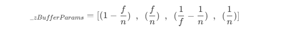
Reversed-Z 优化
- 正交投影下,
z_NDC和z_view是线性关系,而透视投影下,由于z_NDC是按1/z_view关系分布的,因此,z_NDC区间的绝大部分值,都映射到接近近裁剪平面附近,精度较高,而靠近远裁剪平面部分,z_NDC的变化很小,精度较低,即在较大区间范围内的所有z_view都对应同一个z_NDC值,因此容易出现 z-fighting 问题。而在近裁剪平面附近,通常也不需要这么高的精度。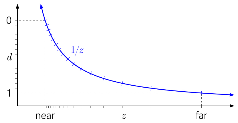
引自 Depth Precision Visualized - 在 D3D 中,
z_NDC的范围为[0, 1],对应z_view的[near, far],而深度值通常使用 4 bit 来存储浮点数。根据浮点数的量化规则,当浮点数越接近 0 时,同样位数的存储能有更大的精度,即能表示更小的浮点数,但这些值对应的z_view变化范围非常小。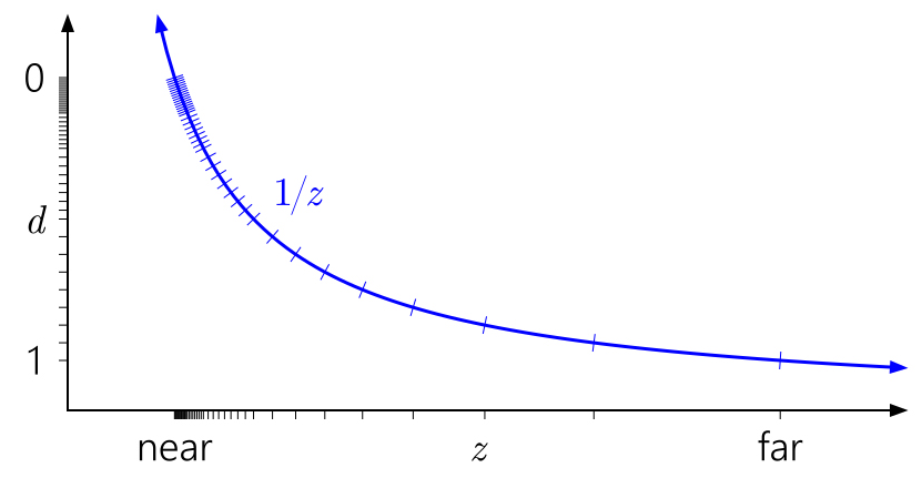
引自 Depth Precision Visualized - 如果将深度值按
1 - z_NDC存储,即远裁剪平面对应z_NDC为 0,利用浮点数的特点,可以在靠近远裁剪平面获得更大的精度,一定程度上抵消非线性深度的问题,这种方式称为Reversed-Z。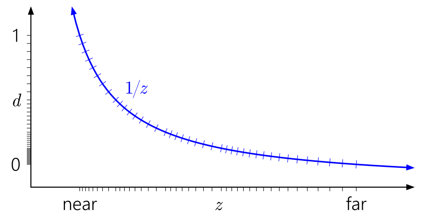
引自 Depth Precision Visualized - 然而,在 OpenGL 中,由于
z_NDC的范围为[-1, 1],浮点数的高精度部分集中在中间区域,远裁剪平面无法通过使用Reversed-Z优化。尽管z_NDC在后续会将值映射到[0, 1]存入深度纹理,但由于初始映射到[-1, 1]的过程已经破坏了远裁剪平面部分的精度,所以Reversed-Z作用不大。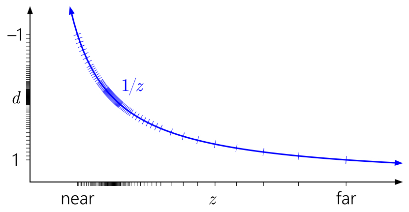
引自 Depth Precision Visualized
观察坐标重构
- 根据近裁剪平面上的顶点坐标信息,加上深度纹理的
uv坐标和深度信息,可以计算出目标点在观察空间下的坐标(参考SSAO.hlsl中的ReconstructViewPos方法)。
// ./ShaderLibrary/SSAO.hlsl

...

half3 ReconstructViewPos(float2 uv, float linearDepth)
{
    #if defined(SUPPORTS_FOVEATED_RENDERING_NON_UNIFORM_RASTER)
    UNITY_BRANCH if (_FOVEATED_RENDERING_NON_UNIFORM_RASTER)
    {
        uv = RemapFoveatedRenderingNonUniformToLinear(uv);
    }
    #endif

    // Screen is y-inverted.
    uv.y = 1.0 - uv.y;

    // view pos in world space
    #if defined(_ORTHOGRAPHIC)
        float zScale = linearDepth * _ProjectionParams.w; // divide by far plane
        float3 viewPos = _CameraViewTopLeftCorner[unity_eyeIndex].xyz
                            + _CameraViewXExtent[unity_eyeIndex].xyz * uv.x
                            + _CameraViewYExtent[unity_eyeIndex].xyz * uv.y
                            + _CameraViewZExtent[unity_eyeIndex].xyz * zScale;
    #else
        float zScale = linearDepth * _ProjectionParams2.x; // divide by near plane
        float3 viewPos = _CameraViewTopLeftCorner[unity_eyeIndex].xyz
                            + _CameraViewXExtent[unity_eyeIndex].xyz * uv.x
                            + _CameraViewYExtent[unity_eyeIndex].xyz * uv.y;
        viewPos *= zScale;
    #endif

    return half3(viewPos);
}

...
- 对于正交投影,目标点观察空间下的
x、y坐标,可由近裁剪平面的左上顶点的x、y坐标,加上uv偏移得到,z坐标则可由近裁剪平面的z坐标,加上当前和近裁剪平面的距离得到,即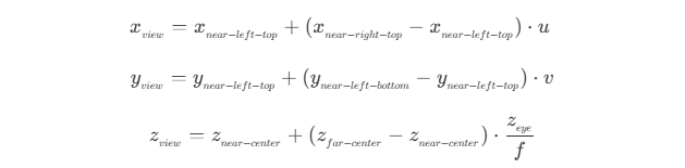
- 对于透视投影,根据变换的关系,可以得到观察空间下目标点的坐标和其投影到近裁剪平面上的点的坐标关系
 同样使用近裁剪平面的左上顶点和
 uv偏移,则有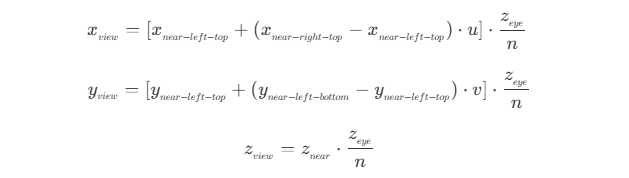
法线重构
- 根据顶点坐标信息,加上深度纹理的
uv坐标和深度信息,可以计算出目标点在观察空间下的法线(参考SSAO.hlsl中的ReconstructNormal方法)。
// ./ShaderLibrary/SSAO.hlsl

...

half3 ReconstructNormal(float2 uv, float linearDepth, float3 vpos, float2 pixelDensity)
{
    #if defined(_SOURCE_DEPTH_LOW)
        return half3(normalize(cross(ddy(vpos), ddx(vpos))));
    #else
        float2 delta = float2(_SourceSize.zw * 2.0);

        pixelDensity = rcp(pixelDensity);

        // Sample the neighbour fragments
        float2 lUV = float2(-delta.x, 0.0) * pixelDensity;
        float2 rUV = float2(delta.x, 0.0) * pixelDensity;
        float2 uUV = float2(0.0, delta.y) * pixelDensity;
        float2 dUV = float2(0.0, -delta.y) * pixelDensity;

        float3 l1 = float3(uv + lUV, 0.0); l1.z = SampleAndGetLinearEyeDepth(l1.xy); // Left1
        float3 r1 = float3(uv + rUV, 0.0); r1.z = SampleAndGetLinearEyeDepth(r1.xy); // Right1
        float3 u1 = float3(uv + uUV, 0.0); u1.z = SampleAndGetLinearEyeDepth(u1.xy); // Up1
        float3 d1 = float3(uv + dUV, 0.0); d1.z = SampleAndGetLinearEyeDepth(d1.xy); // Down1

        // Determine the closest horizontal and vertical pixels...
        // horizontal: left = 0.0 right = 1.0
        // vertical  : down = 0.0    up = 1.0
        #if defined(_SOURCE_DEPTH_MEDIUM)
             uint closest_horizontal = l1.z > r1.z ? 0 : 1;
             uint closest_vertical   = d1.z > u1.z ? 0 : 1;
        #else
            float3 l2 = float3(uv + lUV * 2.0, 0.0); l2.z = SampleAndGetLinearEyeDepth(l2.xy); // Left2
            float3 r2 = float3(uv + rUV * 2.0, 0.0); r2.z = SampleAndGetLinearEyeDepth(r2.xy); // Right2
            float3 u2 = float3(uv + uUV * 2.0, 0.0); u2.z = SampleAndGetLinearEyeDepth(u2.xy); // Up2
            float3 d2 = float3(uv + dUV * 2.0, 0.0); d2.z = SampleAndGetLinearEyeDepth(d2.xy); // Down2

            const uint closest_horizontal = abs( (2.0 * l1.z - l2.z) - linearDepth) < abs( (2.0 * r1.z - r2.z) - linearDepth) ? 0 : 1;
            const uint closest_vertical   = abs( (2.0 * d1.z - d2.z) - linearDepth) < abs( (2.0 * u1.z - u2.z) - linearDepth) ? 0 : 1;
        #endif

        // Calculate the triangle, in a counter-clockwize order, to
        // use based on the closest horizontal and vertical depths.
        // h == 0.0 && v == 0.0: p1 = left,  p2 = down
        // h == 1.0 && v == 0.0: p1 = down,  p2 = right
        // h == 1.0 && v == 1.0: p1 = right, p2 = up
        // h == 0.0 && v == 1.0: p1 = up,    p2 = left
        // Calculate the view space positions for the three points...
        half3 P1;
        half3 P2;
        if (closest_vertical == 0)
        {
            P1 = half3(closest_horizontal == 0 ? l1 : d1);
            P2 = half3(closest_horizontal == 0 ? d1 : r1);
        }
        else
        {
            P1 = half3(closest_horizontal == 0 ? u1 : r1);
            P2 = half3(closest_horizontal == 0 ? l1 : u1);
        }

        // Use the cross product to calculate the normal...
        return half3(normalize(cross(ReconstructViewPos(P2.xy, P2.z) - vpos, ReconstructViewPos(P1.xy, P1.z) - vpos)));
    #endif
}

...
- 初级版本,计算相对简单,仅对当前坐标点计算了
ddx和ddy,得到当前坐标点到水平、垂直方向相邻点的向量,再进行叉乘计算,即得到当前点、水平相邻点、垂直相邻点组成的三角面的法线。- 其中相邻点为 GPU 执行时的 2 x 2 单元块。
- 尽管计算简单,但在深度不连续的边缘处,偏导跨越了不同表面,法线会扭曲。
- 中级版本,取上下左右距离当前点两个像素的 4 个点,采样计算其线性深度,分别取水平和垂直方向中线性深度较大的两个点,和当前点组成的三角面,以三角面的法线为当前点的法线。
- 取线性深度大(即距离相机远)的点,是因为当采样点的线性深度越大,越不容易出现在当前点的前方。而在当前点前方的点,越容易为其他物体,因此计算得到的法线错误率更高。而在当前点后方的采样点,如果为其他物体,则两点之间存在边缘,此时计算得到的法线也能相对接近实际法线。
- 相比初级版本,需要进行深度图的多次采样,性能开销上会增大。
- 高级版本,则是在中级版本上对采样点最改进,上下左右取了 8 个点,如果某一侧连续的三个点的深度差为越小,则越接近同一平面,计算得到的法线则越接近真实结果。
- 相比中级版本,采样点翻了一倍,所以性能开销上会更大,但相对地能得到一个更加准确的结果。
法线纹理
- 在 Built-In 管线中,法线没有单独的纹理,如果需要法线,则会将法线和深度一起存储到深度法线纹理中,存储时通过
EncodeDepthNormal方法,将深度编码到RG通道,将法线编码到BA通道,读取时再通过DecodeDepthNormal进行解码,得到深度和法线。其中,法线的编码方法EncodeViewNormalStereo为
// UnityCG.cginc

...

inline float2 EncodeViewNormalStereo( float3 n )
{
    float kScale = 1.7777;
    float2 enc;
    enc = n.xy / (n.z+1);
    enc /= kScale;
    enc = enc*0.5+0.5;
    return enc;
}
- 单位法线向量的点落在单位球面上,以
(0, 0, -1)为投影中心,z = 0为投影平面,将所有点投影到投影平面上,则有
x_0、y_0为投影平面上点的坐标,z_o为投影中心点的z坐标,即
- 在 URP 中,法线则是通过
DepthNormalOnlyPass,渲染所有对象的DepthNormals或DepthNormalsOnly标签的pass,结果写入到深度图_CameraNormalsTexture中。
总结
- 深度和法线纹理,随着版本的变更,也出现了一些新的调整,但其原理基本上是相同的。了解深度法线纹理的生成过程,对于复杂效果的实现有比较大的帮助。